Creo Sheet Metal Flange Vs Flat

Engine In Creo 3d Modeling Tutorial Parametric Mechanical Design
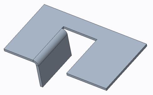
About Attached Flat And Flange Walls

Solidworks Sheet Metal 2d To 3d Sheet Metal Drawing Solidworks Solidworks Tutorial

Difference Between Flat Wall And Flanged Wall Sheetmetal Proe Creo
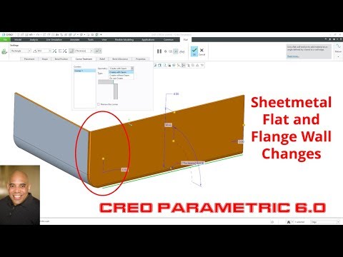
Creo Parametric 6 0 Sheetmetal Flat And Flange Wall Changes Youtube

Solidworks Panosundaki Pin
Below is the basic example of the flat and flanged walls.
Creo sheet metal flange vs flat.

Drawing Reading L 3d Modeling L Design Intent Solidworks Tutorial In 2020 Solidworks Tutorial 3d Modeling Tutorial Mechanical Design

Sheet Metal Flat States
About Bend Relief

Creo Sheetmetal Extrude Planar Flat And Flange In Sheet Metal Youtube
Source : pinterest.com
